
Reifen-Innentrommel-Prüfstand (IPS)
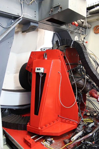
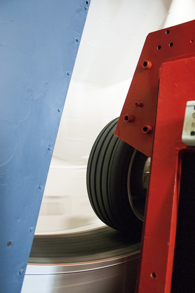

Am Innentrommelprüfstand (IPS) läuft der Reifen bei diesem Prüfstand, durch eine entsprechende Radaufhängung geführt, auf der Innenseite einer zylindrischen Trommel mit 3,8 m Durchmesser. Dieser relativ große Durchmesser hat den Vorteil, dass die Eigenschaften von Reifen in Pkw-Dimensionen durch die Trommelkrümmung praktisch nicht beeinflusst werden. Ein weiterer Vorteil dieses Prüfstandaufbaus liegt darin, dass es möglich ist, auf der Innenseite der Trommel einen sehr gleichmäßigen Wasserfilm aufzubauen, so dass der Einfluss der Nässe auf den Kraftschluss der Reifen untersucht werden kann. Des Weiteren sind Messungen auf vereister Fahrbahn und auf Schnee möglich, da die gesamte Trommel mit einer im Prüfstand integrierten Kältemaschine auf 40° C unter Umgebungstemperatur abgekühlt werden kann.
Die Einstellung der Radlast, des Schräglauf- und des Sturzwinkels erfolgt mit Hilfe von geeigneten hydraulischen Regeleinrichtungen. Bei Umfangskraftmessungen wird das Prüfrad mit einem Hydraulikmotor angetrieben oder gebremst.
Die am Rad angreifenden Kräfte und Momente werden mit einer 6-Komponenten-Meßnabe gemessen, die zwischen Rad und Radlagerung angeordnet ist und deren Meßsystem mit Raddrehzahl mitrotiert. Dadurch werden nur die am Rad angreifenden Kräfte und Momente ohne Beeinflussung durch die Antriebswelle gemessen, wobei die störende Radlagerreibung eliminiert wird. Die gemessenen Daten werden im TYDEX-Format abgespeichert.
Within the inner drum test rig, the tire is guided by a corresponding suspension and runs on the inside of a cylindrical drum with a diameter of 3.8 meters in this test stand. This relatively large diameter has the advantage that the properties of tires in passenger car dimensions are practically not influenced by the curvature of the drum. Another advantage of this test stand setup is that it is possible to build a very uniform water film on the inside of the drum, allowing the influence of wetness on tire traction to be investigated. Furthermore, measurements on icy roads and snow are possible because the entire drum can be cooled up to 40°C lower than the ambient temperature using a refrigeration machine integrated into the test stand.
The adjustment of the wheel load, camber angle, and toe angle is carried out with the help of suitable hydraulic control devices. For circumferential force measurements, the test wheel is driven or braked by a hydraulic motor.
The forces and moments acting on the wheel are measured with a 6-component measuring hub, which is arranged between the wheel and the wheel bearing, and whose measuring system rotates with the wheel speed. This allows only the forces and moments acting on the wheel to be measured without being influenced by the drive shaft, while the disturbing wheel bearing friction is eliminated. The measured data is stored in TYDEX-Format.
| Mechanischer Aufbau Mechanical construction |
Wert Value |
|---|
|
Trommel-Innendurchmesser Drum inner diameter |
3,80 m |
|
Fahrbahnbeläge Road surfaces |
Safety-Walk |
|
versch. Betonbeläge various concrete surfaces |
|
|
versch. Asphaltbeläge various asphalt surfaces |
|
|
Höchstgeschwindigkeit Maximum speed |
|
|
-auf Safety-Walk on Safety-Walk |
200 km/h |
|
-auf Asphalt / Beton on asphalt/concrete |
150 km/h |
|
Wasserhöhe Water depth |
0 ... 4 mm |
|
Umgebungstemperatur Ambient temperature |
-20 ... +30 °C |
|
Schräglaufwinkel Slip angle |
-20° ... +20° |
|
Sturzwinkel Camber angle |
-10° ... +20° (+20° ... +45°) |
| Messsystem für Kraftschluss Measuring system for adhesion |
|---|
Rotierendes 6-Komponenten-Messystem:
Rotating 6-component measuring system:
Max. Radlast, Seitenkraft, Umfangskraft:
Max. wheel load, lateral force, circumferential force:
15 kNMax. Antriebsmoment, Sturzmoment
Max. driving torque, overturning moment
5500 NmMax. Rückstellmoment
Max. aligning moment
1500 Nm
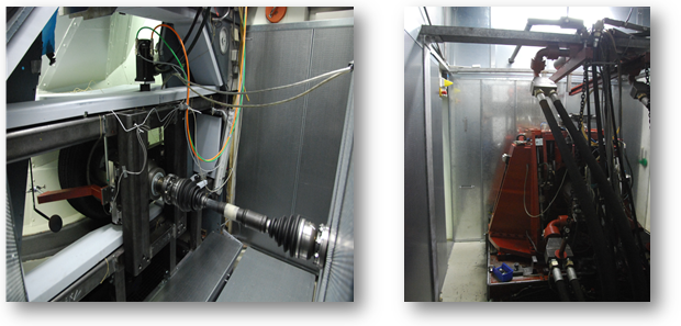
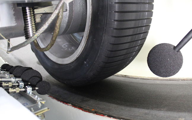
Spezialaufbau für NVH Messungen
Special setup for NVH measurements
- Antriebsachse ist durch eine elastisch verformbare Scheibe mechanisch entkoppelt
- Reduzierung des Körperschalls: Radkasten wird mit dem Hydraulikmotor auf einer dämpfenden Fußbefestigung gelagert
- Anpresskraft wird durch eine elektrisch angetriebene Kugelgewindespindel erzeugt
- Schalldämmung: Unterteilung der Gesamtversuchseinrichtung in Messkabine und Aggregat
- Absorptionsmodule erzeugen einen reflexionsarmen Raum
- The drive axle is mechanically decoupled by an elastically deformable disc.
- Reduction of structure-borne noise: The wheel arch is mounted on a damping foot attachment with the hydraulic motor.
- Contact pressure is generated by an electrically driven ball screw spindle.
- Sound insulation: Division of the overall test facility into a measurement chamber and equipment.
- Absorption modules create a low-reflection space.